38 Results
View results:
Sort by:

Spreadsheet programs like MS EXCEL are very popular with engineers because they allow you to simply automatize your calculations and quickly output the results. Therefore, combining MS EXCEL used as a graphical interface with Dlubal's WebService API is an obvious choice. By using the free xlwings library for Python, you can control EXCEL, and read and write values. The functionality is described in the following, using an example.

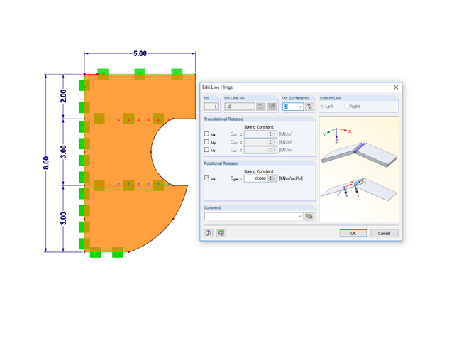
Line releases are special objects in RFEM 6 that allow structural decoupling of objects connected to a line. They are mostly used to decouple two surfaces that are not rigidly connected or transferring only compressive forces at the common boundary line. By defining a line release, a new line is generated at the same place which transfers only the locked degrees of freedom. This article will show the definition of line releases in a practical example.

This article shows you how to define different types of member transverse stiffeners in RFEM 6 and RSTAB 9. It also shows you how to consider them in the design as well as the calculation of members with 7 degrees of freedom.

This article will show you how to use the Torsion Warping (7 DOF) add-on in combination with the Structure Stability add-on to consider cross-section warping as an additional degree of freedom when performing the stability analysis.
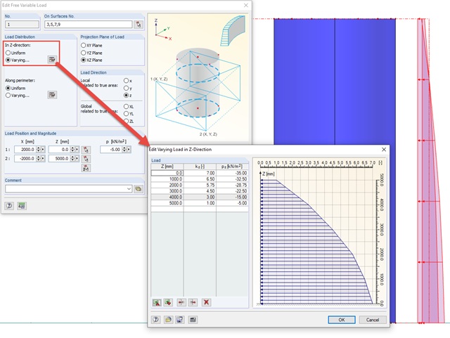
In order to apply loads that are variable in height and perimeter to rotationally symmetric objects, RFEM provides the free variable load.

A member's boundary conditions decisively influence the elastic critical moment for lateral-torsional buckling Mcr. The program uses a planar model with four degrees of freedom for its determination. The corresponding coefficients kz and kw can be defined individually for standard-compliant cross-sections. This allows you to describe the degrees of freedom available at both member ends due to the support conditions.

In RF-/STEEL EC3, sets of members are calculated according to the General Method (EN 1993-1-1, Cl. 6.3.4) together with the stability analysis. To do this, it is necessary to determine the correct support conditions for the equivalent structure with four degrees of freedom. In most 3D models today, you can quickly lose track of the location of a set of members in the system.
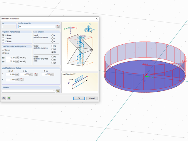
In RFEM, loads can be freely defined on surfaces. It is impossible, however, to define a variable loading on, for example, circular surfaces. However, you can still create this type of loading by using a free circular load.
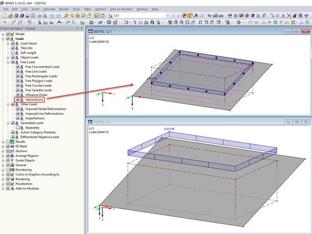
For free loads, RFEM allows you to display the intersections at the respective surface.

To simulate a support clearance in a connection between members, you can use the "Diagram" function for member hinges. To use this function, first define the relevant degree of freedom as release. Then, you can select the "Diagram" function from the drop‑down list.

In RF-/FOUNDATION Pro, the user can freely select the proportion of the relieving soil pressure by means of the factor kred.
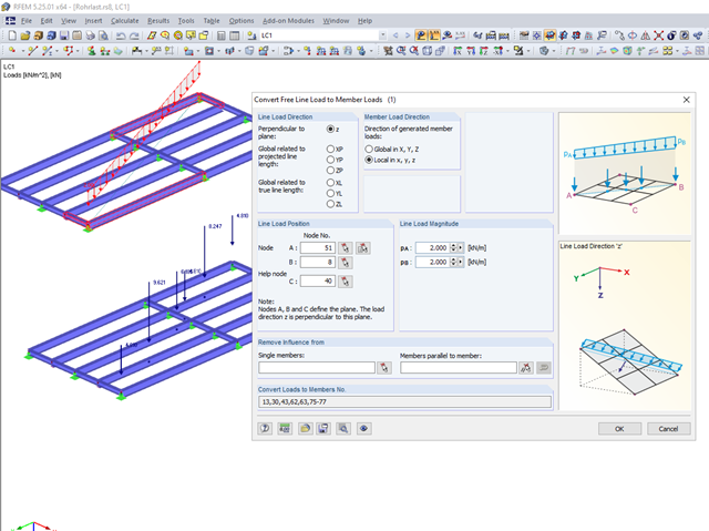
Not all structural elements of a real building are included in a structural model. As an example, we can look at a pipe that runs along a steel girder frame.
One of the advantages of entering the structure in RFEM is the complete freedom when selecting the geometry. You can easily select a structure where re‑entrant rolling corners are given as shown in the image.

You can use the "Free Circular Load" option in RFEM to apply a partial uplift force to a cone‑shaped floor slab. It can be defined as linearly variable. The definition of center C and the outer boundary R can be specified easily, using the select function.
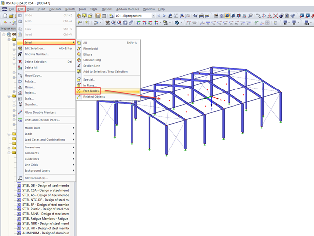
When you finish modeling a structure, it can often happen that some unused nodes remain in the model.

In order to detect the governing internal forces of a plate, a checkerboard loading is commonly used. Since it is not necessary to divide the surface into individual load segments, loading is usually carried out by means of free rectangular loads. In the case of many loads, the normal load display can become somewhat confusing.

Often in RFEM, only part of a surface must be loaded, not an entire surface. A typical case of this is soil pressure. For this purpose, there is the option of defining free surface loads. They are surface-independent and are displayed in defined coordinate dimensions in the graphic.
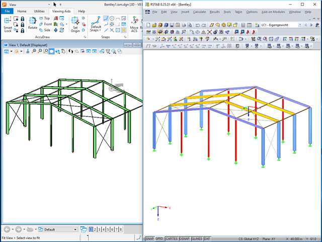
The ISM file (ISM = Integrated Structural Modeling) in RFEM and RSTAB provides an interesting option for exchanging data. If you export a model to this data format, you can view and analyze it with the free ISM viewer from Bentley.
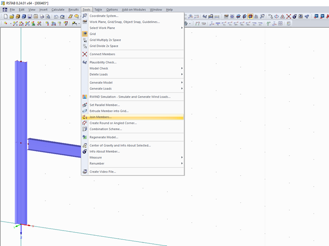
To join free members to the members located within a certain maximum distance, use the "Join members" function.
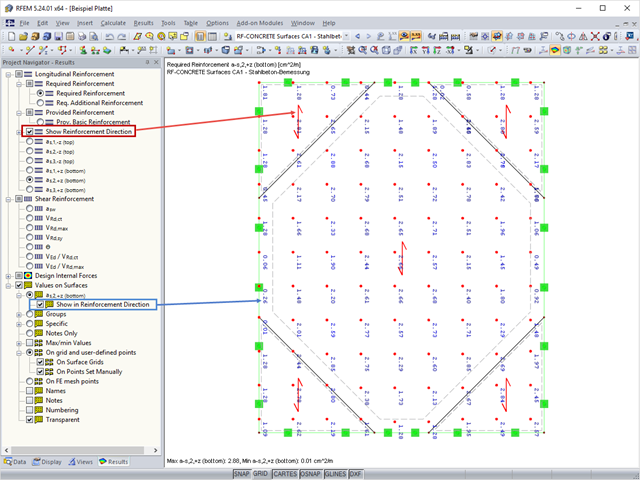
In RF‑CONCRETE Surfaces, the design of the surface reinforcement is done by means of a freely definable reinforcement mesh. In RF‑CONCRETE Surfaces, you can display the reinforcement direction by activating the reinforcement arrow that represents it.
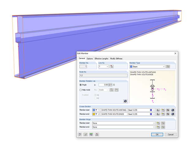
In RFEM and RSTAB, you can analyze members with a variable cross-section, which can also consist of freely defined SHAPE-THIN cross-sections. The cross-section properties are interpolated in order to determine the internal forces and deformations.

The design of a torsional loaded beam according to AISC Design Guide 9 will be shown, based on a verification example. The design will be performed with the RF‑STEEL AISC add-on module and the RF‑STEEL Warping Torsion module extension with 7 degrees of freedom.
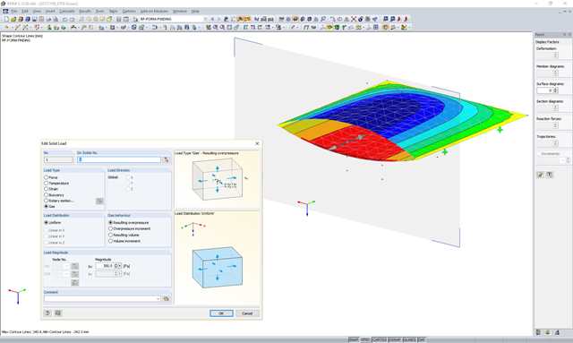
In theory, an ideal gas consists of freely moving mass particles without extension in a volume space. In this space, each particle moves at a speed in one direction. The collision of one particle with another particle or the volume limitations leads to a deflection and a change in the speed of the particles.
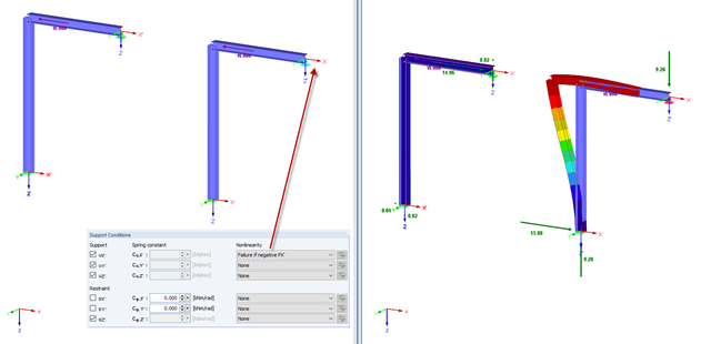
In practice, an engineer often faces the task of representing the support conditions as close to the reality as possible in order to be able to analyze the deformations and internal forces of the structure subjected to their influence and to enable construction that is as cost-effective as possible. RFEM and RSTAB provide numerous options for defining nonlinear nodal supports. The first section of my article describes the options for creating a nonlinear free support and provides a simple example. For a better understanding, the result is always compared to a linearly defined support.
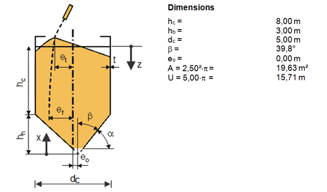
The previous article described the actions on silos according to DIN EN 1991-4. On an example of a free standing cylindrical silo for cement with a conical hopper, filling loads of the silo hopper were calculated.
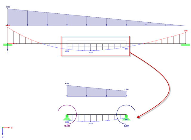
This article explains how to determine loads on the basis of the internal force situations defined in the RF‑/STEEL Warping Torsion extension of the RF‑/STEEL EC3 add-on module. Since this new program also allows you to analyze extracted chain-like beam structures in addition to entire chain-like beam structures, it is necessary to determine the loads of the partial structure separately. To do this, a special transformation function has been developed that determines new loads of all partial structures (depending on the internal forces calculated in RFEM/RSTAB) according to each load situation for geometrically nonlinear warping torsion analysis with seven degrees of freedom.
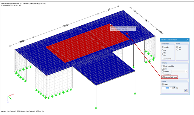
In RFEM and RSTAB, you can add user‑defined dimension lines to a structural model. When creating these dimension lines, click the objects (for example, end nodes of a line, members, and so on) that represent the reference points of the dimension. If you want to add a dimension line free from the structure previously defined in the model, you have to create an additional free "help node" that acts as a reference object for the new dimension.
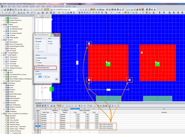
In order to set a dimension in RFEM, a physical node must exist at the locations to be dimensioned. Therefore, dimensioning free surface loads or graphical results was impossible without further effort until now.

The form-finding process in RF-FORM-FINDING displaces the corner nodes of FE elements of a membrane surface in space until the defined surface stress is in equilibrium with the boundary conditions. This displacement is independent of the element geometry. In the case of elements with four corner nodes, the free displacement may cause spatial drilling in the element plane and thus exceed the validity limits of the calculation; therefore, triangular elements are generally recommended for form‑finding systems. Triangular elements remain independent of the corner node displacement and stay within the calculation limitations.
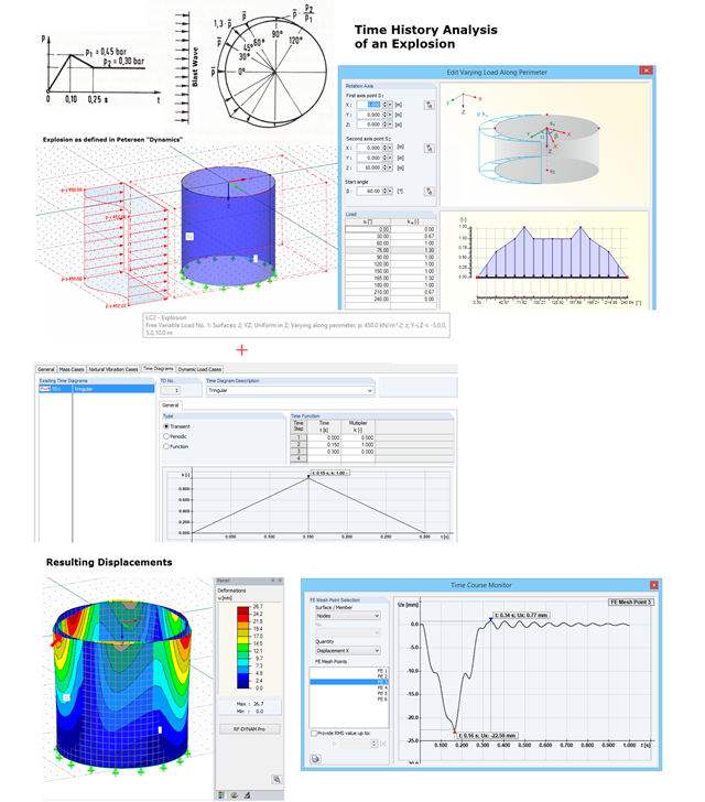
With RF-DYNAM Pro – Forced Vibrations, you can perform a time history analysis. For example, you can analyze an explosion acting on a nearby building structure. In "Dynamik der Baukonstruktionen" by Christian Petersen, formulas for time diagrams and load distribution are described to specify an explosion. The image shows the input of such an explosion load. Free variable loads are available in RFEM that enable flexible load distributions.